안녕하세요~
기묘한 주제로 오늘은 ~~ 찾아뵙습니다~아
요즘은 서버하면 Unix 서버보다 x86 계열을 서버를 주로 많이 쓰잖나요
(저만 그런건 아니겠죠;;;)

하하 각설하고요.
x86을 쓰다 보면 제일 많이 얻어 맞는 장애는 Disk fault 그리고 메모리 ECC인데요.
ECC는 간단히 말해서 여분의 전송 BIT를 가지고 문제가 생기는 BIT의 오류를 교정하는 것입니다. 아우...이걸 어떻게 쉽게 얘기할수 있을지...ㅠㅠ
요즘 추세로 제일 이해하기 쉬운건 RAID5 디스크 처럼 생각하시면 되요~~!

여튼...그래서 두개의 BIT의 문제가 생기면 해당 오류를 정정할수가 없기 때문에 시스템이 현재 상태를 보호하기 위해서 다시 시작되게 되거든요. 원래는 이랬었어요
근데요 최근에 다른 방법으로 정정하는 기술들이 나와서 소개합니다.
정확하게는 최대한 시스템에 영향을 안 주고 넘어갈수 있도록 조정한거지만요!
내용은 이렇습니다.
ü 기술적으로 많은 경우 CPU가 해당 데이터를 patch하여 사용하기 때문에 UC Uncorrected Error 에 속하여
시스템이 다시 시작하게 됩니다. 하지만, 시스템이 데이터를 아직 patch하지 않은
경우에는 다시 시작하지 않을 가능성이 있는 조건인 UCR Uncorrected Recoverable Error
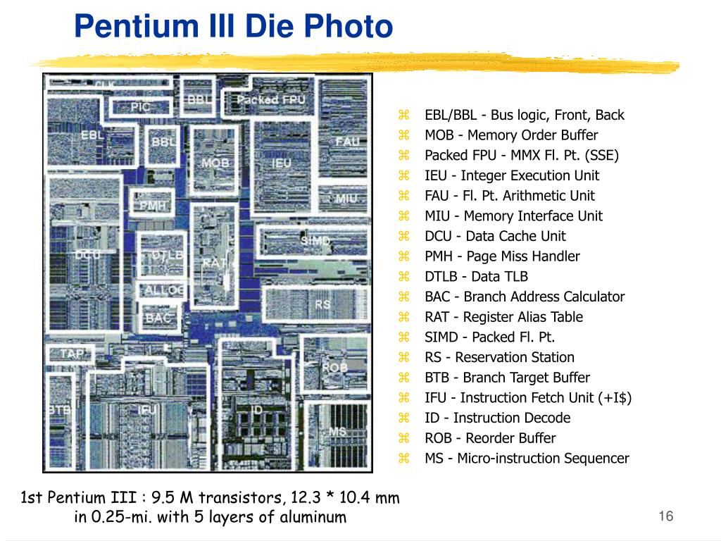
에 속하게 됩니다. 이 중에 DCU Data Cache
Unit와 IFU Instruction Fetch Unit에 의해서 발견된 것은 SRAR Software Recoverable Action 에 속하게 되고, 이 경우에는 두가지 경우가 있는데, kernel
space일 경우에는 kernel panic이 발생하게 되고 user
space인 경우에는 해당 프로세스를 죽이게 됩니다.
ü 따라서, 현재의 경우에는 높은 가능성으로 SARO Software
Recoverable Action Optional에 속하게 되는데, 이는 Memory patrol scrub 기능 또는 LLC Last
Level Cache 의 writeback 트랜잭션시에 발견되게 됩니다.
이 경우에는 kernel space 일 경우이거나, user space일 경우 페이지 Page자체를 모두 무시하거나 격리처리하게 됩니다. |
되게 어렵죠 -_-?
이거 영문을 거의 그대로 번역해서 그런건데요 그나마 이해하고 써도 이정도로..어렵...
쉽게 다시 설명하면요. 메모리는 CPU에서 쓰고자하는 내용을 CPU내부의 register와 sram 이후로 가장 빠르게 접근할수 있는 영역인데요.
그래서 CPU가 가져다가 참조하고 있는 것들이라면, 그건 고대로 Reboot합니다.
우리가 알고 있는거죠! 여기까지는 문제 없죠?
자 그러면...
CPU가 아직 참조하지 않은 메모리에 담긴 데이터가 1) DCU Data Cache Unit와 2) IFU Instruction Fetch Unit 에 의해서 Multibit 에러가 발견되게 되면요. 두가지 방식으로 동작하게 되는데요.

Kernel panic = 우리가 알고 있는 리부우우우트
User space = 프로세스만 킬 (근데 DB단이라면 -_- OMG)...뭐 rollback해서 보호하거나 commit 안했을테니모..
그리고, Memory patrol scrub 기능 또는 LLC Last Level Cache 의 writeback 트랜잭션시 에 의해서 발견하게 되면요.
page 자체를 격리해 버려요. 있잖나요 디스크의 Bad Sector를 막아버리는 것처럼? 요즘 SSD도 비트가 flap을 못하면 막도만요~~ 수명이 있는거니까
이건 시스템에 아무런 영향이 없어요~그리고 사실 Page isolation이니까 다시 시작하게 되면 어짜피 reset 될꺼에요.
근데 Multibit 에러가 난 메모리는 시스템이 다시 시작할때 교체해 두는게 좋겠죠?
이번에는 운이 좋았던거에요~!
이를 표로 정리하면 이렇게 되요.

재미있지 않나요~ :)
또 변화한 신기한 이야기가 있다면 또 쓸께요~~!
==========================
1) DCU
Data Cache Unit
The Data Cache Unit (DCU) consists of the following sub-blocks:
- The Level 1 (L1) data cache controller, that generates the control signals for the associated embedded tag, data, and dirty RAMs, and arbitrates between the different sources requesting access to the memory resources. The data cache is 4-way set associative and uses a Physically Indexed Physically Tagged (PIPT) scheme for lookup that enables unambiguous address management in the system.
- The load/store pipeline that interfaces with the DPU and main TLB.
- The system controller that performs cache and TLB maintenance operations directly on the data cache and on the instruction cache through an interface with the IFU.
- An interface to receive coherency requests from the Snoop Control Unit (SCU).
The data cache has the following features:
- Pseudo-random cache replacement policy.
- Streaming of sequential data because of multiple word load instructions, for example
LDM,LDRD,LDPandVLDM. - Critical word first linefill on a cache miss.
See Chapter 6 Level 1 Memory System for more information.
If the CPU cache protection configuration is implemented, the L1 Data cache tag RAMs and dirty RAMs are protected by parity bits. The L1 Data cache data RAMs are protected using Error Correction Codes (ECC). The ECC scheme is Single Error Correct Double Error Detect (SECDED).
The DCU includes a combined local and global exclusive monitor, used by the Load-Exclusive/ Store-Exclusive instructions. See the ARM® Architecture Reference Manual ARMv8, for ARMv8-A architecture profile for information about these instructions.
A2.1.1 Instruction fetch
The Instruction Fetch Unit (IFU) fetches instructions from the L1 instruction cache and delivers up to three instructions per cycle to the instruction decode unit.
The IFU includes:
- A 64KB, 4-way, set associative L1 instruction cache with 64-byte cache lines and optional dual-bit parity protection.
- A fully associative instruction micro TLB with native support for 4KB, 64KB, and 1MB page sizes.
- A 2-level dynamic branch predictor.
3) LLC
메모리 계층도에서 보면 가장 상위층에 존재하는 레지스터 다음에 캐시가 존자한다. 이 캐시도 세부적으로 분류할 수 있다. 보통 컴퓨터를 살때 보면 L1,L2와 같이 캐시가 얼마다 라고 적혀 있는 것을 확인 할 수 있을 것이다. 일반적으로 현대 프로세서는 L1,L2 두개로 구성되어 있고 L3캐시까지 있는 CPU 도 볼 수 있을 것이다. 즉 L1이 가장 성능이 좋을것이고 그다음 순차적으로 좋을것이다. 여기서 마지막 레벨에 있는 캐시를 Last Level Cache (LLC)라고 부른다. LLC이후에는 시간이 오래 걸리므로 캐시와 구분해서 계층도에서 표시된다.
And Wirteback
In a conventional writeback policy, dirty cache blocks are
sent to the write buffer when they are evicted from the lastlevel cache (LLC). The write buffer is drained following the
buffer management policy. Several proposals [16, 18, 13]
improve writeback efficiency using an intelligent scheduling
algorithm. However, the write buffer only has a small number of entries due to design complexity and power efficiency,
limiting the ability to schedule high locality write requests as
well as the possibility to flexible adjust read/write priority


Reference:
https://cesl.tistory.com/entry/Cache-정리 [Embedded Lab]


